Tracing a Source Image
A scan, photograph, or imported drawing can supply the starting shape for a glyph. Place the source in the Glyph window, size it against the font's metrics, then trace it by hand or use Autotrace to generate editable contours.
Autotrace follows the image, including its defects. Treat the result as preliminary drawing material: inspect its silhouette, counters, corners, and point structure before using it in a finished font.
Placing a Source Image
Prepare the source and choose its fitting behavior before placing it in the font.
Common bitmap sources include PNG, JPEG, and TIFF. Vector artwork can arrive through SVG, PDF, or supported Illustrator artwork. Clipboard exchange from applications such as Illustrator, Affinity Designer, and Sketch depends on the vector formats they place on the clipboard. FontLab can also place PDF drawing data on its clipboard for use in other graphics applications.
A bitmap needs tracing to become editable contours. Imported vector artwork may already contain editable paths or may remain a placed SVG requiring conversion. Check what you have imported before choosing Autotrace.
Prepare a clear bitmap
Use an image with clear foreground and background separation. For lettering on paper, grayscale scanning retains edge information better than an already thresholded, rough black-and-white scan. Draw large enough that the intended edge is visible; lettering around two inches high is a practical starting size for scanning, not a required physical size.
Choose pixel dimensions appropriate to the intended drawing. At a one-pixel-to-one-font-unit placement, a capital 700 pixels high occupies 700 font units. Leave space between letters if a scan contains several glyphs, so later separation can distinguish them.
Crop unnecessary borders and remove obvious dirt before tracing. FontLab's Image panel provides filters that can help clean a source (see Working with Color Images), but smoothing or thresholding can also change corners and narrow gaps. Compare the prepared image with the original drawing.
Choose how artwork fits the font
Under Preferences > Paste & Duplicate > Fit artwork, Method controls scaling and placement. Check this before importing a source whose intended size is important.
| Method | Intended fitting behavior |
|---|---|
| Do not scale or align | Preserves source size and placement rather than fitting to a metric span |
| Align only | Preserves size and aligns the artwork to the origin reference |
| UPM height from descender | Fits the artwork to a height of one em, starting at the descender |
| Descender to Ascender | Fits the artwork between those two lines |
| Baseline to Caps Height | Fits the artwork between baseline and cap height |
| Descender to Caps Height | Fits the artwork between descender and cap height |
The metric-span choices preserve proportions while fitting the height. UPM height from descender means a span equal to UPM; its upper position is Descender + UPM, not necessarily y = UPM.
Bitmap pixels provide the source coordinate scale, but Fit artwork can apply a transform to a bitmap as well as to vector artwork. Do not assume that a 700-pixel image will always appear 700 font units high. Clipboard bitmap placement can also reduce an oversized image in an unscaled placement path. Check the placed image against the rulers and dimension lines, especially when changing between import, drop, and paste methods.
The fitting calculation uses the source bounds. Inspect the placed result against the intended design dimensions. Crop or correct the source bounds, then place it again if necessary.
For vector artwork intended as ordinary monochrome contours, enable Preferences > Paste & Duplicate > Vector artwork > Ignore stroke and colors. This discards the source's appearance information when the supported vector import path creates the contours. Check outlined strokes, counters, and clipping effects afterward; the appearance of a graphics document and its underlying paths need not be identical.
After preparing the source and choosing the fitting settings, open the target glyph. Choose File > Import > Artwork… and select the source file, or drag or paste the artwork into the Glyph window. Check its size and position against the font’s reference lines before tracing.
Autotracing a Bitmap
Start with one representative image so you can tune the settings before processing a whole set.
- Select the placed bitmap in the Glyph window; its context menu provides the tracing command.
- Choose Element > Image > Autotrace…, or use Autotrace… in the image's context menu.
- Inspect the contour preview on the canvas.
- Select PS contours in Trace result is, then adjust the trace and simplification controls described below.
- Choose Keep, Remove, or Move to Mask for the source image. Keep the original image file if you may need another trace.
- Click OK to retain the result, or Cancel to discard the preview and restore the source display.
If the preview is too small to judge, cancel, zoom closer, and reopen the dialog. Inspect a curve, a sharp corner, and the narrowest counter rather than judging only the overall silhouette.
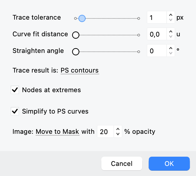
Autotrace puts trace quality and source-image handling in one dialog. This example uses PS contours and Move to Mask; tune the values against the canvas preview.
Adjust the trace
The three principal controls change the compromise between following the source and simplifying it:
| Control | What to assess in the preview |
|---|---|
| Trace tolerance (pixels) | How closely the result follows small edge details; a larger value permits a looser fit |
| Curve fit distance (units) | The amount of curve-fitting simplification; larger values permit fewer, less exact segments |
| Straighten angle (degrees) | Angular tolerance for straightening corners and near-axis segments |
Change one control at a time. A close fit can preserve noise and produce too many nodes; a loose fit can remove a needed corner or close a narrow opening. The controls tune the tracer rather than promising an exact maximum geometric error in the final transformed drawing.
Scaling a placed image on the canvas changes the traced result's size, but does not create additional source detail. The tracer works from the underlying bitmap and applies the placement transform to the contours. For a different source resolution, resample or rescan the image before tracing.
Choose and inspect the curve result
Use PS contours in Trace result is for this workflow. The current tracer generates cubic outlines. Although the selector also lists TT contours and Lines only, do not rely on the selected label alone to establish the resulting curve type; inspect the generated contours. If you require a different geometry, convert the resulting contours afterward and inspect the conversion.
Nodes at extremes requests points at horizontal and vertical extremes. Additional cleanup can also insert extreme points, so turning the option off does not guarantee a result without them.
Simplify to PS curves applies a further simplification pass. It can reduce redundant points and regularize the result, but check that it has not weakened distinctive details. A smaller node count is useful only when the contour still describes the intended shape.
Keep, remove, or retain the source as a reference
Choose the source-image action before confirming:
- Keep leaves the bitmap alongside the traced contours.
- Remove removes the placed bitmap after tracing. Retain the original image file if you may need another trace.
- Move to Mask keeps it in the glyph's mask as a comparison reference, separate from the main drawing.
The image-opacity value controls how strongly a retained source appears. A subdued source can make it easier to compare the traced edge without hiding the contours. For using masks as drawing references, see Design References and Comparing.
After confirming, select the Contour tool and inspect the nodes. Check closure, direction, counters, unintended fragments, and small irregular curves. Autotrace can reproduce a scan accurately while still producing a poor font outline; the next work is deliberate editing. Continue with Basic Node and Handle Operations, Structural Soundness, and the measurement aids in Live Measurement.
Batch-tracing and SVG Conversion
Trace several glyphs
In the Font window, select the glyphs containing the source bitmaps and choose Element > Image > Autotrace…. The dialog supplies one set of settings for the batch. There is no single-glyph live canvas preview in this route, so establish suitable values on a representative glyph first.
Review the settings—including Keep, Remove, or Move to Mask—before clicking OK. The operation processes applicable images in the targeted glyph layers. Inspect several results afterward, including the lightest, darkest, and most detailed source glyphs; one setting may not suit every image equally.
For a single image containing multiple glyphs, Element > Image > Separate and Trace combines optical separation with tracing. Optical separation is covered in Working with Color Images; the staging canvas is covered in The Sketchboard. Tune the trace on a representative image first, and inspect the separated pieces before relying on the result as a glyph set.
Make an SVG editable
Select a placed SVG and choose Element > Image > Make SVG Editable. This converts the available vector drawing into editable content; it does not need to infer an edge from pixels.
Check the result at the placed size. SVG transforms are taken into account during conversion, and hidden objects declared with display="none" are excluded. Complex appearance features may not reduce to the simple monochrome outline you expect, so compare the converted drawing with the source before discarding that source.
If the SVG was already imported as editable paths, there is no placed SVG left to convert. Select its contours and continue with ordinary outline editing.