Basic Node and Handle Operations
Use the Contour tool to move points, change how segments meet, or alter the structure of a path. Start with a small, explicit selection and check the filled result after each structural change.
Moving Points and Point Selections
Drag a node to move it and its attached handles. Drag a handle to change the adjacent curve. On a smooth node, the opposite handle stays aligned through the node, though its length need not match.
For a group move, select the required points first and drag from a selected point. Dragging an unselected point can change the selection. The point you grab acts as the reference for snapping; watch its position as well as the overall selection.
Hold Shift for constrained movement. Ordinary point movement is constrained horizontally or vertically; handle movement has its own angle constraints. Hold Control to suspend snapping during a drag. On macOS, Control and Command have different roles: Command invokes the precision lever, while Control supplies the snapping override.
Move by measured steps
With the canvas in editing focus, the arrow keys move the selection. The usual steps are one font unit for an arrow and ten for Shift+Arrow; the distances are configurable in Preferences > Distances. For the 100-unit step, use Cmd+Arrow on macOS or Shift+Ctrl+Alt+Arrow on Windows. Read the coordinates if movement differs from the expected step.
| Movement | macOS | Windows |
|---|---|---|
| Small step, normally 1 unit | Arrow | Arrow |
| Large step, normally 10 units | Shift+Arrow | Shift+Arrow |
| 100-unit step | Cmd+Arrow | Shift+Ctrl+Alt+Arrow |
For direct placement, use the selection's x and y fields in the property bar. Check whether the fields are showing absolute positions or relative movement before entering a number. For a multi-point selection, the reference point determines which part of the selection the position describes. The Contextual widget also provides position fields beside the drawing.

The Contextual widget shows X and Y for one node.
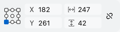
For several points, the Contextual widget adds a reference-point selector, width, and height.
Contour > Coordinates > Follow Italic Angle makes vertical movement follow the font's italic angle. It does not slant the entire drawing. With integer rounding enabled, a very small vertical step may have no visible horizontal component because that component rounds to zero. A slanted grid display and slant-aware movement are separate settings.
Whole-stem editing
The Stem tool (6) selects detected strokes in an outline, so you can move, change the thickness of, or rotate a stem without first selecting its individual points. Its selection model and modifiers differ from the Contour tool. For the complete procedures, numeric controls, keyboard operations, and spacing behavior, see The Stem Tool.
Aligning Points
Use Contour > Align Points for exact alignment. What the command aligns depends on the selection:
- With a partial point selection, Left or Right brings points to a common x position; Top or Bottom brings them to a common y position.
- With several complete contours selected, the contours align as units.
- With one complete contour selected, the same commands use the glyph's metric framework: Left and Right use its side boundaries, Bottom uses the baseline, and Top uses Caps height.
Auto chooses a nearby horizontal or vertical alignment for points; for one complete contour, it centers the contour within the advance width. Center and Vertical Center provide explicit centering choices. The Transform panel offers corresponding alignment controls. Same Width and Same Height resize complete selected contours to a common dimension; they are not merely positional alignment. Use a complete-contour selection, apply the appropriate command under Contour > Align Points, then inspect the changed shapes as well as their alignment.
Inspect the selection before aligning. Moving a complete contour to the baseline is different from making all of its nodes share one y coordinate. Likewise, aligning a round letter to a design-height line can remove an intentional overshoot, introduced in Hinting and the Pixel Grid; the command does not decide which optical correction your design needs.
Adding and Deleting Points
To insert a node, hold Control+Option on macOS or Ctrl+Alt on Windows and click directly on the segment. A curve receives a smooth node; a line receives a corner. Clicking near the path can invoke a different operation, so use the pointer's target indication.
Add Shift to insert an appropriate extremum, a local top, bottom, left, or right extreme, on a PS curve when available. On a TT curve, the gesture can insert an implied on-curve point. This targets a geometrically determined position rather than necessarily the exact pointer position.
Remove a node without opening the path
Select the node and press Backspace. FontLab reconnects the neighboring parts of the contour and tries to retain the shape. On a Mac keyboard, the key commonly labeled Delete is this backward-delete key.
Reconnection is an approximation when a point carries necessary shape information. Check the resulting curve and undo if the silhouette changes more than intended. Removing a node from an already open path does not make the whole path closed automatically.
Delete and open the path
The forward Delete key performs the breaking form of deletion. On a compact Mac keyboard, use Fn+Delete. This leaves an opening rather than reconnecting the path in the same way as Backspace.
Do not treat these two keys as interchangeable. After either operation, inspect the endpoints and fill.
Remove or restore handles
Shift+Option/Alt-click a handle to remove it without deleting its parent node. This can turn the associated curve into a line. To retract handles through a command, open the node's context menu and choose Handles > Retract.
An Option/Alt-drag from a corner node can pull out a retracted handle. Watch which side of the node is being affected before completing the drag.
Changing Node Type
Double-click a node to switch between corner and smooth behavior. For an explicit choice, select the node or nodes and use Contour > Nodes > Corner or Smooth. A smooth conversion can realign handles and alter the neighboring curves.
Toggle Smooth changes the smooth/corner property more conservatively, without the same immediate conversion of adjoining segment types. Detect Smooth finds geometrically aligned corner nodes and assigns smooth behavior. Inspect the result rather than assuming that every visually gentle join has been recognized.
The immediate Smooth/Corner operations are eager conversion: they can adjust handles and neighboring segment types. Toggle Smooth is the lazy conversion route: it changes the property without the same segment-type conversion. It does not act on a node between two straight segments. Converting a corner node to smooth and back restores its original handle direction.
Use these distinctions when the drawing already has a useful shape. If the intention is to identify an existing aligned join as smooth, inspect Detect Smooth or the conservative toggle. If the intention is to change the construction, an immediate conversion may be appropriate. After either route, examine both neighboring segments rather than only the node marker. A marker reports a relationship; it is not a guarantee that the complete curve is well drawn.
Contour > Convert > To Corner is a different construction operation. It replaces a selected segment, or an open path's endpoint gap, by extending adjacent segments to their intersection and placing a corner there. It changes the path geometry rather than merely assigning a node property. Compare the result and undo if that extension is not intended.
Breaking and Joining
Select a node and choose Contour > Break (Cmd+B on macOS, Ctrl+B on Windows). The node becomes two coincident endpoints. Breaking one point opens a closed contour; breaking several points can create several open paths.
Select two open endpoints and choose Contour > Join (Cmd+J or Ctrl+J). Coincident endpoints merge into one point. Separated endpoints are connected by a straight segment. Joining the two ends of the same path closes it; joining ends from different paths combines them.
The new connection can change the silhouette or introduce a corner. Inspect it at a useful zoom before continuing. The arrow-shaped endpoint markers identify an open path; recall the open/closed distinction in Contours, Nodes, and Handles. Ordinary filled-outline production requires closed contours, so check closure again after editing.
Breaking and joining serve different construction purposes. Breaking gives access to a section without necessarily moving its endpoints. Two endpoints can occupy the same coordinates and still belong to an open path: touching positions do not by themselves establish a closed connection. Joining makes the structural connection explicit. If the endpoints are separated, the added straight segment becomes part of the outline and may need later refinement.
Before joining, check that you selected the intended pair. In a crowded drawing, nearby endpoints can belong to different contours. Compare the connection with the intended silhouette, then inspect the other ends of the affected paths. A successful join of two paths does not imply that the combined path has no remaining open ends. Keep the distinction between the local operation and the state of the whole contour.
Setting the Startpoint
Select the node that should begin a closed contour's sequence, then choose Contour > Set Start Point. Enable View > Contours > Contour Direction if you need to see the start marker clearly.
With no point selected, Set Start Point chooses a suitable start for each contour in the current drawing layer, favoring corner nodes on line segments near the origin. Make a selection when you want one specific contour and point.
Changing the start point changes point order without moving the closed outline. That order can matter to interpolation and point-based font data, so preserve it deliberately when such relationships already exist. Open contours also have a first point, but their endpoints define the path's beginning and end. Matching masters is covered in Interpolation and Compatibility; hinting and point-based relationships are developed in Hinting and the Pixel Grid and The TrueType Hinting Model and Workspace.
Use a deliberate start point when contour order is part of another relationship. A closed outline is cyclic: it can have the same shape while its stored sequence begins at a different node. That means a visual comparison of filled glyphs alone may not reveal the change. Inspect the start marker and contour direction as well as the silhouette.
For a simple drawing without dependent point references, choosing a convenient start can make later inspection easier. For related masters or already instructed outlines, consider those dependencies before changing order. Work on a saved source and compare the affected designs afterward. Set Start Point is a structural choice, not a repair for a badly shaped curve or an inconsistent direction. Choose the operation that matches the problem rather than using it merely because the marker appears inconvenient.
Italic-angle setup is covered in Preparing for Italics; alignment zones are developed in Alignment Zones and Standard Stems.