FontLab 7 Release Notes: Part 3»
Variation, imported artwork, components, auto layers, elements»
- FontLab 7 Release Notes: Part 3
- Variation, imported artwork, components, auto layers, elements
- Variation
- Show inactive layers as wireframes
- Match when Editing
- Copy to Masters
- Conditional glyphs (rvrn, rules)
- Non-matching glyphs in Font window sidebar
- Layers & Masters panel
- Variations panel
- Anisotropic interpolation (separate axis locations for X/Y coordinates)
- Matchmaker
- Sparse masters, intermediate masters
- Vector artwork
- Bitmaps and Autotrace
- Components, Auto Layers and Mark attachment
- Elements
- Stickers
Variation»
- When you create a new font, the default master is now named
Regular. Previously, it was namedBody. - Also see the Variations in Font Info section for more variations-related improvements.
Show inactive layers as wireframes»
When you work with multiple masters, it’s useful to see the contours (a wireframe) of some other masters in the Glyph window for reference. In FontLab 7 you can now control which layers appear filled and which layers appear only as visual references.
Principally, FontLab displays the glyph contents in two different ways in its user interface:
When a glyph is shown as preview, FontLab shows the contours and images fully filled, with the details hidden. They appear as they would print or render when the final font is used in end-user apps. This simulates the end-user’s view. FontLab shows glyphs as preview in the Font window glyph cells, in the Glyph window Text mode, also in the Metrics and Kerning modes (there, some spacing-related details are also shown), in the Glyph window editing modes for non-current glyphs (if Edit Across Glyphs is off), and finally, when you hold ` or Space in the Glyph window. FontLab also shows glyphs as preview in the Preview panel, though here, you can customize the appearance with additional effects.
When a glyph is shown as detailed view, FontLab shows various details of the contours and images in a way suitable for you, the type designer, to draw and edit them. You can fine-tune which details are shown or hidden using the View menu or panel: nodes, handles, master relations, contour direction, coordinates, curvature etc.
Detailed view shows glyph contours:
- filled, which is either fully filled (if View > True Fill is on), or semi-filled (Preferences > Glyph Window > Glyph fill controls the transparency)
- unfilled under some circumstances.
In the Layers & Masters panel, you can toggle two properties of a layer that control how the glyphs is shown:
- Service: if on, the layer is not shown in preview. If off, the layer is shown in preview.
- Wireframe: if on, the layer is shown unfilled in detailed view and in preview; instead, the outline of the contours is shown (in both detailed view and preview), drawn in the color that you can assign to the layer in the panel. In detailed view, additional view details (like nodes and handles) can be shown.
The current layer that you work in always appears filled if it is a normal layer (so it’s not marked Wireframe, and is not marked Service).
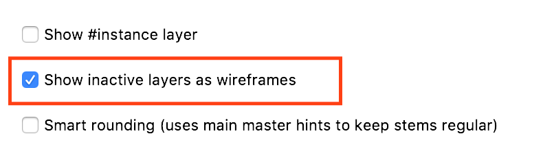
FontLab 7 has a new setting Preferences > Variations > Show inactive layers as wireframes that changes how the Show toggle in the Layers & Masters panel works. If this preference is:
-
On: a normal layer layer that is not current and is visible (the Show toggle shows an open eye in the Layers & Masters panel) will be rendered as wireframe in detailed view, and will not be rendered in preview. This setting is best for variable design, and is new in FontLab 7. You can show/hide nodes and handles in such layers with Preferences > Glyph window > Inactive.
-
Off: a normal, non-current visible layer will be filled in detailed view and in preview. This setting is best for color design, and is the way FontLab VI worked.
Match when Editing»
If you performed certain operations on the current master (adding, renaming or removing a node or guide, adding a hint, adding or renaming an anchor), FontLab VI “repeated” these operations or all matching masters if the settings in Preferences > Variations > Synchronize in matching masters when on.
FontLab 7 still has these settings, but you can now globally turn them on or off with Edit > Match when Editing. When Match when Editing is on, FontLab 7 executes on all matching masters the operations that you perform on the current master and that you’ve enabled in preferences. When you turn off Match when Editing, FontLab will execute those operations on the current master only.
Note
The drawing tools only draw in the current master, even if Match when Editing is on and if Insert node is on in Preferences > Variations > Synchronize in matching masters.
Copy to Masters»
In Glyph window editing modes, when you draw a new contour or element in one master, you can now select it and choose Edit > Copy to Masters (CmdY on Mac, CtrlY on Windows). This will copy the selected objects to all other masters. Note: if choose Copy to Masters several times, FontLab will copy the selected content multiple times.
When you select anchors and pins, and and choose Edit > Copy to Masters, FontLab will:
- add the anchors/pins to the other masters if those masters don’t contain anchors/pins with a given name
- update the position of these anchors/pins with corresponding names that exist on the other masters
In Metrics mode of the Glyph window, Edit > Copy to Masters only copies expressions (metrics links) from the current master to all other masters. It does not simple sidebearing or width values.
Conditional glyphs (rvrn, rules)»
FontLab now lets you export Variable OpenType fonts in which some input glyphs are replaced with some “conditional” glyphs in a specific region of the design space. These conditional glyph substitutions happen when the dynamic instance selected by the end-user fulfils one or more conditions. This is realized with the OpenType rvrn (required variations) feature and uses the DesignSpace rules functionality.
To use conditional glyph substitution, you cannot create the rvrn feature in the Features panel, as there is no FEA syntax that can express the conditions. Instead, you need to assign “tilde tags” to the conditional glyphs, i.e. the “target” glyphs which will appear under some conditions.
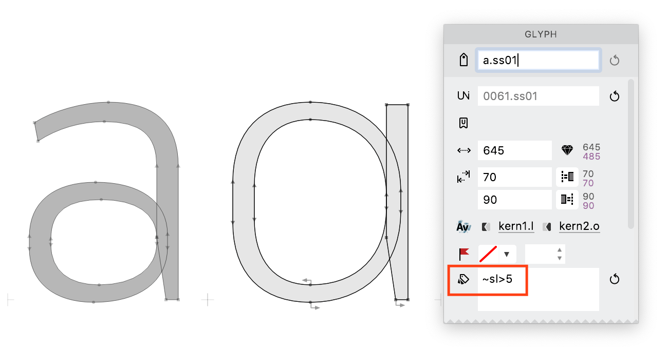
Select these glyphs in Font window, then open the Classes panel, switch to Tags, add a tilde tag that describes the condition (see below) and drag-drop the selected glyphs from the Font window. Alternatively, open the Glyph panel, and in the Glyph tags field, type the title tag prefixed by + to assign the tag to the selected glyphs.
Tilde tags»
The syntax for tilde tags is the following: inputglyph~conditionset, where conditionset is one ore more condition expressions concatenated with & (so: condition&condition..., for example e~wt>820&wd<110. Specifically:
-
If
inputglyphis absent, the name of the conditional glyph (the glyph that has the tilde tag) without the suffix will be used as the input glyph. For example, to replaceewithe.ss04when the weight axis is 820 or more, assign the tilde tag~wt>820to thee.ss04tag. Sincee.ss04without the suffix ise, you don’t need to specify the input glyph. -
The
conditioncan have the form eitherax>minorax<maxormin<ax<maxormax>ax>min. -
axis the axis code, same as the axis code that appears in master and instance locations; e.g.wtfor weight. minandmaxare axis locations expressed in design coordinates, same as master and instance locations.- The
>and<actually inclusive, so they are equivalent to the mathematical ≥ and ≤ operators. - To specify a
conditionsetfor multiple axes, so that the conditional substitution happens only in a region enclosed by multiple axes (logical “and”), concatenate (glue) multipleconditionexpressions (one per axis) with&. One axis code can only appear once in a tilde tag, so use the200<wt<700form rather thanwt>200&wt<700.
To specify a conditional substitution that happens when one conditionset is met or when another other conditionset is met, add multiple space-separated tilde tags, one per conditionset.
For example, to replace e with e.ss04 when the weight axis is 820 or more and the width axis is 110 or less, or when the weight axis is 750 and the width axis has any value, enter +~wt>820&wd<110 +~wt>750 in the Glyph tags field of the Glyph panel for the e.ss04 glyph.
- When FontLab exports Variable TT or Variable PS fonts, it converts the tilde tags into the
rvrnfeature. - When FontLab exports static fonts (instances), it performs the conditional substitution by remapping Unicode codepoints in the affected instances.
- When FontLab opens
.designspacefiles, it converts theruleselement into tilde tags. - When FontLab exports DesignSpace + UFO, it converts the tilde tags into the
ruleselement. - When FontLab opens a Variable OpenType font that contains the
rvrnfeature, it converts are glyph-to-glyph substititions specified in this feature into tilde tags.
Notes about conditional glyph substitution»
Conditional glyph substitution in variable fonts works like any other 1:1 OpenType substitution (for example for small caps). In static instances, FontLab reassigns the Unicode codepoint from the input glyph to the output glyph. Both glyphs that participate in conditional glyph substitution remain in your font, and you can use them in other OpenType features. If you want kerning, you need to assign them to kerning classes, and kern them as you wish. FontLab does not to any “magic” here.
You can only specify conditional glyph substitutions where one glyph is replaced by another glyph. To use ligature substitutions, you need to manually write the conditions into the GSUB table using the TTX notation in the Tables panel.
Conditional substitutions only work when the input glyph has a Unicode codepoint. This is because with variable OpenType fonts, text layout apps execute the rvrn feature at the beginning of the OpenType processing, immediately after Unicode codepoints are converted to the default glyphs. So you cannot, for example, substitute an oldstyle nine.onum by nine.onum..rvrn if nine.onum is the result of a substitution in the onum feature. With static fonts, FontLab also only remaps glyphs with Unicode codepoints, so the behavior is consistent.
There is a way to work around this limitation: create a conditional glyph nine.rvrn that is identical to nine and is substituted when the conditions are met. Then in onum, substitute nine with nine.onum that has one shape, and nine.rvrn with nine.rvrn..onum that has another. This is similar to the popular technique for Turkish ligatures, where you create i.loclTRK as an identical duplicate of i, substitute it in the locl feature for Turkish, and then, in the liga feature, only form ligatures with i but not with i.loclTRK.
Only those glyphs that have the tilde tags will be substituted — not the composite glyphs that use them. If you want to use an alternate “a” above weight 650, and you also want to use the same alternate shapes for “àáâä” etc., you can do two things:
- Create a full set of target composites, the same as you’d do for a stylistic set. Use the same suffix (such as
.rvrnor perhaps something like.ss05if you also want to make these alternates explicitly available in a stylistic set. Then create a tag~wt>650in the Classes panel, and drag all the.rvrnglyphs to it. This will assign the tilde tag to each of those glyphs. If the glyph name portion before the suffix matches the full glyph name of another glyph, the glyph with the suffix will replace the glyph without the suffix when the conditions are fulfilled. - Alternatively, only create one alternate glyph with the base letter (such as
a.rvrn) and assign the tilde tag to it. Then, use anchors so that FontLab generates mark attachment. Caution: if you wish to export a variable font with mark attachment, you need to duplicate the default Variable TT or Variable PS export profile, and in the customized profile, turn on Features and Kerning > OpenType mark attachment > Always create [mark/mkmk] code. You need matching anchors in all masters, otherwise the export of the variable font may fail.
If you assign the tilde tag ~wt>650 to a.rvrn, the a glyph will be replaced by a.rvrn when the weight is 650 or more. But you can assign multiple tilde tags to the target glyph:
- To specify different source glyphs, enter the source glyph name before the tilde. So if you assign the tilde tags
~wt>650,b~wt>650,c~wt>650toa.rvrn, thena,bandcwill be replaced bya.rvrnwhen weight is 650 or more. - To specify alternate conditions, assign multiple tags. For example, in a two-axis font, assign the tags
~wt>650and~wt>600&wd>110toa.rvrn, andawill be replaced witha.rvrnwhen weight is 600 or more and width is 100 or more, or when weight is 650 or more regardless of width. The conditions are processed from the most specific to the most general one. It’s not possible to create “diagonal” conditions, but by combining more and less specific conditions, so you can create “staircase” patterns of conditions.
Non-matching glyphs in Font window sidebar»
The Font window sidebar now has a new font window filter that shows glyphs that have non-matching (incompatible for interpolation) masters.
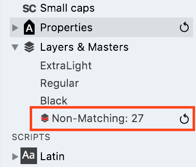
To see it, expand the Layers & Masters section of the Font window sidebar (double-click it or click the triangle).
The new Non-matching entry is listed after the list of all layers found in the font. The entry shows the number of glyphs with non-matching masters, so if you see 0 there, all your glyphs can be properly interpolated.
- Click the Refresh button next to the entry to update the filter.
- If the number is larger than 0, click the Non-matching entry, and all glyphs that have non-matching masters will be shown on top of the Font window in the highlighted section (or only those glyphs will be shown if Hide unfiltered glyphs is on).
Layers & Masters panel»
In the Layers & Masters panel, you can now assign colors to layers more easily:
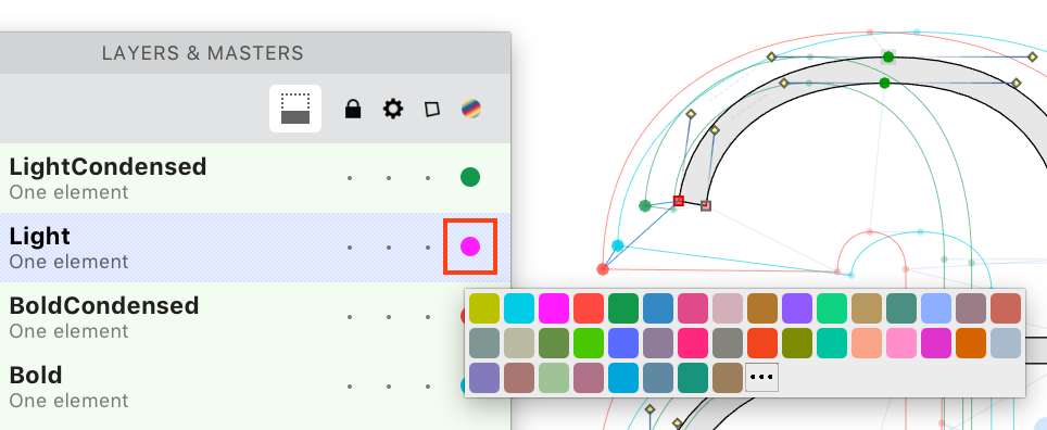
- When you click the color dot at the right side of the layer entry, you can choose the color from a list of predefined colors, or click ⋯ to open the system color picker. Previously, clicking the color dot opened the system color picker directly.
- When you click the heading of the color dot column, FontLab automatically chooses a unique color for the current layer.
- When you Cmd-click (Mac) / Ctrl-click (Win) the heading of the color dot column, FontLab automatically chooses unique colors for all layers (except the Mask layers).
Layer colors are not exported into the final fonts. You can use layer colors to visually distinguish between the masters or layers, as you design your glyphs. You can see the layer colors:
- When you make a layer Wireframe (by clicking in the Wireframe column of the Layers & Masters panel), the glyph contours will be drawn using the layer color and without fill.
- When you turn on Preferences > Variations > Preview master color, the Glyph window will show the layer color as a bar at the top of the window or as the window’s background.
When a master matches the current master only thanks to auto matching, its background color in the Layers & Masters panel is now a more contrasting orange rather than pale yellow.
Variations panel»
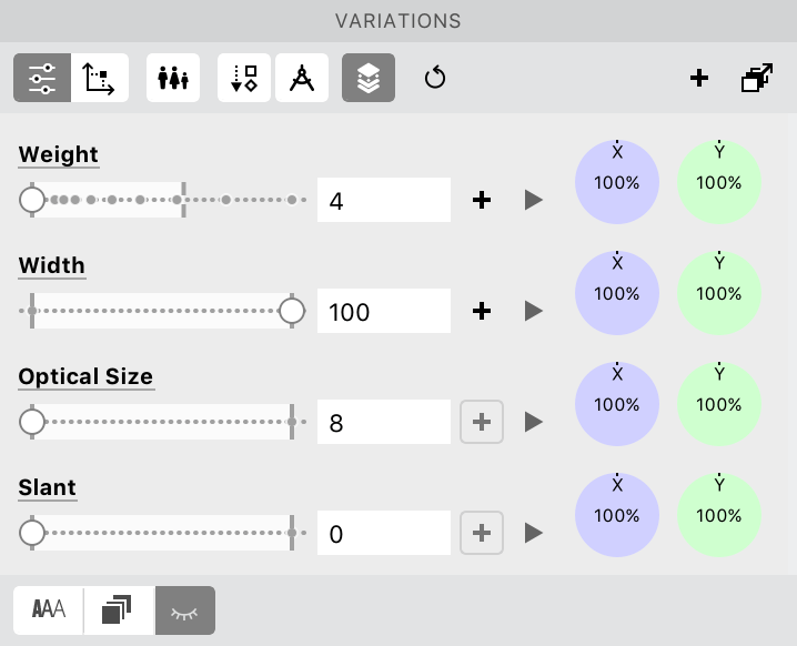
- The top-left toggle for switching between the List view and the Map view now uses icons rather than text labels.
- In List view, the bottom toggles let you switch between showing masters, showing instances, or hiding the lower portion.
- In List view, when you click the name of the axis, axis instance selectors are now sorted by location on the axis, not alphabetically.
- In List view, masters and instances in the lower portion show their axis locations in the same order as the axes order set in Font Info > Axes.
- When you click Add Glyph(s) Master, the proposed name of the glyph master layer sorts the axis locations in the same order as the axes order set in Font Info > Axes.
Anisotropic interpolation (separate axis locations for X/Y coordinates)»
When the Variations panel is wide enough, the List view shows a green and a blue dial.
You can use these dials for anisotropic interpolation, where you specify the axis location for the X coordinates of all points separately from the axis location for the Y coordinates of all points. The dials work so that you can “amplify” or “tone down” the X and Y interpolation values relatively to the interpolation location that you choose with the axis slider.
Anisotropic interpolation does not affect variable fonts, but you can use to it create a static font from the current dynamic instance, and add the current dynamic instance as a master.
When the X/Y dials are in non-default positions, numeric values appear above the axis location value that show the actual axis location that will be used for the X and the Y coordinate. Double-click the dial to reset its position to 100% (which is normal interpolation).
The Font > Generate Instance dialog now also has anisotropic interpolation dials, so you can easily add an anisotropically interpolated instance as a master or create a static font from it.
Matchmaker»
The Matchmaker tool (Tools > Tools > Matchmaker) shows the current glyph’s masters that are set as “visible” in the Layers & Masters panel. You can drag the Matchmaker vector to offset the masters visually, you can inspect how nodes and contours in all the masters match.
Matchmaker also lets you perform partial manual matching of masters: mark corresponding sections on each master: first drag around each corresponding node on all masters (this gives you a blue selection), then drag around each corresponding node several segments fruther on all masters (this gives you an organge selection). Finally, click on either selection. Matchmaker will add or remove nodes on each section (series of segments) on each master between those two “selections”
In FontLab 7, the Show intermediates toggle in Matchmaker works differently:
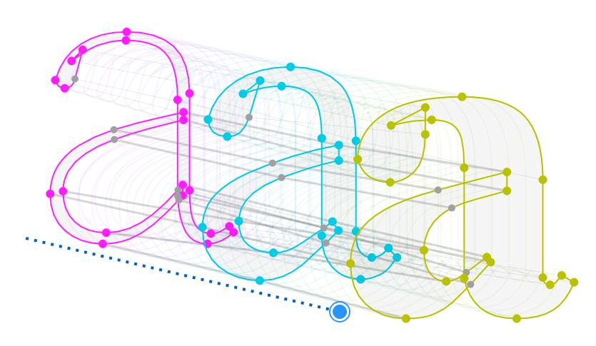
- On: Matchmaker colorizes all contours in each master with the color defined in the Layers & Masters panel, and shows the intermediate interpolations. You can change their number, and set its opacity to 0 to hide them. The intermediates are not the same as instances, since Matchmaker arranges all masters into one “virtual axis” in equal steps, in the order set in Font Info > Masters, so you can move a Black master between Light and Regular, and check the interpolation coming directly between Light and Black.
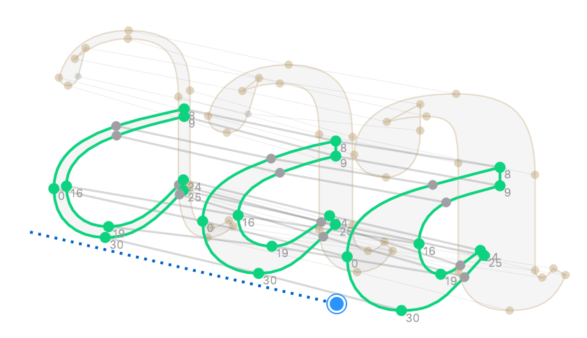
- Off: Matchmaker shows node numbers, so you can easily see missing or superfluous nodes. It colorizes each matching contour across all visible masters with a unique color, so you can easily see the contour order. When you select at least one node with the Contour tool in a glyph that has multiple contours, Matchmaker will highlight that contour across all visible masters. Use the Elements panel to drag-drop the contours to change the order of the contours.
If a Glyph window has Text > Echo Text on and Matchmaker is active, switching glyphs in another Glyph window correctly switches the glyph shown with Matchmaker.
Note
Trying to use Matchmaker to manually match masters that are already are fully compatible can lead to non-matching masters. This is by design. Matchmaker always assumes that the current state is not satisfactory, so it’ll use its heuristics to change the current state. If your contours are fine, don’t use Matchmaker.
Sparse masters, intermediate masters»
Font masters are “sub-fonts” within your FontLab font. They contain font names, font metrics, font guides, kerning classes and kerning pairs. When a font master is marked with a blue “AAA” icon in Font Info > Masters, that master is variable, i.e. it takes part in variation that lets you generate instances through interpolation.
All glyph layers that have the same name as a font master belong to that master. When the glyph layers that belong to a variable font master match, they can interpolate, i.e. generate an instance. In addition, glyphs can have variable font-less masters, i.e. layers named with a colon followed by a list of comma-separated pairs of axis tags and axis locations, e.g. :wt=350,wd=100.
A font master that has corresponding layers in all glyphs is called a complete font master. If a font master has fewer corresponding glyph layers than there are glyphs in the font, it’s called a sparse font master. A collection of variable font-less masters with the same axes location is called a sparse font-less master.
If you only want to correct the appearance of some glyphs and you don’t need kerning in intermediate masters, it’s best to use a font-less master. FontLab will interpolate all kerning pairs, font metrics etc.
Typically, the “extreme masters”, i.e. masters located at the min or max locations of an axis, are complete font masters, while sparse masters typically are used as intermediate masters, to . To create a sparse font master:
- Choose File > Font Info, click + button at the bottom-left and add an empty master or duplicate an existing master with no glyph layers.
- Go to the Font Info > Masters page, give the font master a name and an axes location, click OK.
- Select some glyphs in the Font window, open the Variations panel, choose a dynamic instance at the same axes location, and click the Add glyph master (+ button in the top-right of the panel). There, enter the name of the font master you’ve just created. This will create interpolated glyph layers in the selected glyphs, and will associate them with the font master.
When you have a sparse font master, you can add kerning pairs to it. Just make sure that your sparse font master has glyph layers for all the glyphs you wish to kern. In Glyph window Text mode, enter the pair combinations, then switch to Kerning mode and click a pair. Now switch to the sparse font master using the master switcher on top of the window or with the Layers & Masters panel, and change the kerning value.
When you export instances or a variable font, FontLab will use the the kerning classes of the main master (shown in bold in Font Info > Masters) and will perform the Font > Kerning > Match Kerning operation which ensures that all masters have the same kerning classes, and fills the missing kerning pairs by interpolation.
FontLab VI allowed you to use sparse (intermediate) masters only when exporting static instances.
In FontLab 7, you can also export fonts that have intermediate masters as Variable TT or Variable PS fonts.
FontLab 7 correctly opens .glyphs brace layers as font-less masters.
Vector artwork»
Copy-paste and import artwork in PDF format»
When you copy a selection from the Glyph window, FontLab now also copies the data as PDF, so you can paste the glyph drawing directly into Adobe Illustrator, Affinity Designer, Sketch, Corel Draw and other vector-editing apps.
You can now also paste PDF clipboard data into FontLab, and import both .pdf files and PDF-compatible .ai files (saved in Illustrator 9 or newer) via File > Import Artwork or via drag-drop onto the Glyph window or onto the Sketchboard.
This means that you can copy-paste from apps like Affinity Designer, Sketch, and many other vector-drawing apps!
The support for PDF paste and import is still a bit experimental, not all drawings or vector artwork will import correctly — so it’s best if you simplify your graphic in the source app as much as possible before pasting.
FontLab 7 does not yet support gradients, it will paste a gradient fill as a solid color fill, where the color is chosen from the middle of the gradient.
Paste/import of vector artwork: Monochrome artwork»
When you paste or import vector artwork (via PDF or the AICB clipboard format), and this artwork has multiple paths that all have the same fill, FontLab now pastes them as one element, so you can immediately edit all contours.
Previously, each path was pasted as a separate element, so you had to choose all elements with the Element tool and choose Element > Combine Contours to Element.
When you paste artwork that has paths with different fills, it’s still pasted as a group of elements, each retaining its color.
Paste/import of vector artwork: Coordinate rounding»
When Contour > Coordinates > Round when Editing is on, FontLab always rounds all node and handle coordinates to integers as you edit them — which is expected in type design. When you paste or imported vector artwork (except SVG), the immediate rounding can introduce distortions if the pasted artwork is small.
Now, when Round when Editing is on and you paste vector artwork, FontLab will show a dialog that lets you choose to Round the coordinates immediately, or temporarily Keep fractional coordinates.
Note
If you choose to keep fractional coordinates, FontLab will round the coordinates when you edit the pasted contours even slightly. So you should turn off Contour > Coordinates > Round when Editing but turn on Preview Rounding. Then, scale the pasted artwork up and down until it has the right size. With Preview Rounding, FontLab shows you the rounded result but keeps the precise coordinates, so scaling is lossless. Once you’re happy, you can Apply Rounding or turn Round when Editing back on.
Improved conversion from SVG to editable contours»
When you import or paste an SVG image, FontLab previews the SVG using a limited previewer so many SVG effects such as gradients will not be visible or will appear garbled. But when you export an OpenType+SVG font, those effects will be correctly retained.
You can transform (scale, rotate, slant) imported SVG images but you cannot edit their contours. However, when you choose Element > Image > Make SVG Editable, FontLab will convert the imported SVG to editable contours. This conversion is now improved. FontLab will correctly handle crops and patterns in addition to strokes and simple fills, but it will still convert gradients to simple fills (the same way as for imported PDF).
Bitmaps and Autotrace»
We’ve improved the Autotrace experience. The process of converting a bitmap image into editable vector contours in FontLab 7 has four steps:
- Prepare the image.
- Build the initial contours around the image.
- Build the final contours by postprocessing the initial contours.
- Postprocess the image.
Prepare the image»
Paste an image into the Glyph window, or import it via drag-drop or File > Import Artwork.
FontLab imports or pastes images so that 1 pixel in the image corresponds to 1 font unit. The Autotrace algorithm operates on the original size of the image. If you scale an image inside FontLab, the autotrace will build the same final contours, but scale them to match the visible image.
You can resample the image in an image editor to a different size, then Autotrace will build different contours. If you’ve imported a low-resolution image, you may scale it up in FontLab and then use Add layer > Rasterize to this PPM: 1000. This will produce a new layer with a resampled image.
You can also try some of the filters from Window > Panels > Image on the image before you autotrace. Use Remove background if your image has visible background. Use Despeckle to remove some stray pixels from the edges. You may also do a Gaussian Blur and then Threshold to sharpen the edges, but this will turn corners into small curves.
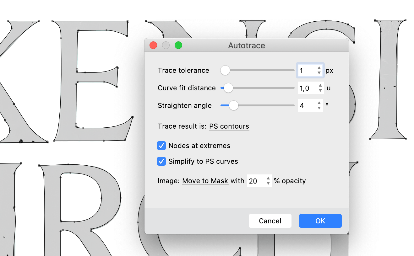
Once you have your image, right-click it and choose Autotrace… or choose Element > Image > Autotrace…. The Autotrace dialog will appear, and in the Glyph window, you’ll see the previewed result of the tracing. If you’d like to see more details, cancel, zoom to the image, and open Autotrace… again.
Build the initial contours»
The Autotrace dialog has three sliders that control the building of the initial contours:
- Trace tolerance is the distance from the image edge to the outline. The default
1follows the image edges closely. Higher values follow the edges more loosely and give more straight lines. - Curve fit distance is the permitted curve approximation error.
0gives many nodes, higher values give fewer curve nodes and flatter segments. The default is2. - Straighten angle is the permitted line approximation error.
0gives almost no straight lines, higher values prefer lines over curves. Default is5.
In the Trace result is, you can decide what form the initial contours will have: PS contours (PostScript curves and lines), TT contours (TrueType curves and lines) or Lines only.
Postprocess the initial contours»
When Autotrace builds the initial contours, you can choose two additional postprocessing steps:
- Nodes at extremes will perform a lightweight simplification of the contours and will add nodes at the outer edges of the contour. If the initial trace result is set to PS contours, this will produce PS contours. If the trace result is set to TT contours, this will produce TT contours. For Lines only, this has no effect.
- Simplify to PS curves will run an additional simplification of the contours. It will also add nodes at extremes, but the final result will always be PS contours.
Experiment with those settings and observe the results — there is no single best default.
Postprocess the image»
You can decide what should happen with the image after Autotrace has built the contours. Previously, the image always stayed on the same layer as the new contours, but this wasn’t practical. Now you can choose to Keep the image in the same layer, Remove it, or Move to Mask (then the image will be moved to the mask layer, so you can keep it as visual reference to manually improve the autotrace result).
You can also choose the opacity that the image will have after tracing. If you’ve imported an image that is very “black”, you may prefer that after Autotrace, when the image is in the Mask layer, it’s lighter (e.g. 20-30% opacity), so it doesn’t visually interfere with your new contours. You can always change the opacity of the image later in the Elements panel.
If you’re happy with the previewed result, click OK. The next time you open Autotrace, the dialog will use your last settings, so you can easily repeat the process with many images.
If you’re not happy with the previewed result, click Cancel and perform some additional image preparation discussed earlier.
More improvements to Autotrace and bitmap images»
-
When you use Element > Image > Separate and Trace (typically on Sketchboard), FontLab will first separate the image into images of single glyphs using the Preferences > Operations > Optical separation settings, and then will autotrace those images using the settings you’ve last used in the Autotrace dialog. So it’s best to first try Autotrace on an image of just one glyph and arrive at settings that make you happy, then bring in a larger image of an entire alphabet, and use Separate and Trace.
-
You can now use Element > Image > Autotrace… in Font window — FontLab will then autotrace all images found in the current layer of all selected glyphs.
-
Since Autotrace now has its own dialog with settings, we’ve removed it from the Image panel, and we’ve removed the autotrace settings from Preferences > Operations.
-
When you paste a bitmap image, FontLab now scales and positions the image according to Preferences > Paste & Duplicate > Scale artwork (when the image is sized at 100%, 1 pixel corresponds to 1 unit). Previously, those settings only worked for vector artwork.
Components, Auto Layers and Mark attachment»
Decomposing composite glyphs»
When you select one or more components in the Glyph window, the Glyph > Decompose operation converts only those components into conoturs. When no components are selected in the Glyph window, or if glyph cells are selected in the Font window, Glyph > Decompose Glyph decomposes all components.
Both commands now affect all compatible masters.
Auto Layers for all masters and multiple glyphs»
To make the current layer of the current glyph an auto layer, or to make it a manual layer, toggle the Auto Layer icon in the Layers & Masters panel (the Show layer properties must be on), or in the Glyph window property bar.
To make the current layer of the current glyph (or, in Font window, of selected glyphs) an auto layer, or to make it a manual layer, choose the Glyph > Auto Layer menu item.
To make all layers of the current glyph (or, in Font window, of selected glyphs) an auto layer or to make all masters “manual” layers, hold Alt, click the Glyph menu, and choose Auto Layer in all Masters. This keeps existing custom recipies in all masters.
To turn on auto layer in all layers of the current glyph and to copy the current layer’s custom recipe to the other masters, or to turn auto layer off, Alt-click the Auto Layer icon in the Layers & Masters panel, or in the Glyph window property bar, or click the Make auto glyph toggle in the Font window status bar (at the bottom).
To edit the custom recipe in all layers of the current glyph, use the Edit recipe button and the Auto glyph recipe field in the Font window status bar.
Flatten Layer and Flatten Glyph»
When you choose Glyph > Flatten Layer, FontLab “flattens” the current layer in the current glyph (or, in Font window, in selected glyphs): it decomposes all components, removes all filters and combines the decomposed elements into a single element.
When you hold Alt and click the Glyph menu, the menu item is called Flatten Glyph. When you choose it, FontLab flattens all layers in the current glyph or in selected glyphs.
Copy recipes»
You can now choose Text > Copy Text As > Recipe to copy the glyph generation recipe for the current glyph layer (in Glyph window), or the selected glyph layers (in the Font window).
- if the glyph layer is an auto layer and has a custom recipe, it will copy that recipe (if the recipe is in the extended syntax, it will prefix it with
!) - if the glyph layer is an auto layer and has no custom recipe, it will copy the built-in recipe
- if the glyph layer is compos ite (only includes components), it will copy a simplified recipe that you can use to recreate the composite glyph (without any coordinate info)
- if the glyph layer is not auto or composite, it will copy the glyph’s name prefixed with
#(i.e. comment)
FontLab automatically chooses whether to use the legacy syntax, or the extended syntax prefixed with !, when copying the simplified recipe for a composite glyph.
Once you’ve copied the recipes, you can paste them into a text editor for editing, or paste them into Font > Generate Glyphs > Custom and generate the glyphs in another font.
Note
If a glyph layer has a custom auto layer recipe but its Auto Layer property is off, FontLab will not copy that recipe but a simplified recipe instead.
Cross-master components»
FontLab 7 introduces cross-master components (this functionality is experimental).
If the glyph has components, in the Elements panel, click Show element properties and then Expand properties. Click a component, and the element properties section will show the new text field Base layer name. Enter a different font master’s name, and the component will point to that master of the source glyph. This may be useful in sparse masters.
Elements»
The Elements panel now has new buttons. In the top section:
- Bring forward, Bring backward, Bring to front, Bring to back / make first. Click those buttons to rearrange the order of the elements or components (you can also use drag-drop or Element > Arrange). Elements and components in the Elements panel are listed in the visual stacking order, so the “first” element/component is shown at the bottom of the list.
In the element properties section: Expand element transformation. If the element has a the live (dynamic) shift, scale, flip, rotation and slant that is applied, click this to convert the apply that transformation onto contours. FontLab will permanently modify the point coordinates, and round them to integers if Contour > Coordinates > Round when Editing is on. Then it will reset the element transformation. Same as Element > Expand transformation.
In the bottom section:
- Expand filters: if the element has glyph filters (Fill, Smart Corners, Power Brush, Glue), click to apply these filters to the element contours, and to remove the filters. Same as Element > Expand Filters.
- Remove filter: if the element has glyph filters, click to remove the filters without applying them to the contours. This will convert the element to simple contours. Same as Element > Remove Filter.
Stickers»
In FontLab, you can place stickers (text annotations with arrows) inside the Glyph window. Choose Element > New sticker (or press CtrlT), and a sticker with your text appears.
You can resize the sticker using the gray handles at the corners. You can pull out arrows from the color dots on its corners and sides, or double-click the color dot to remove the arrow. In the Elements panel, you can click the colored circle next to the sticker to change its color. Double-click the sticker text to edit it.
In FontLab 7, you can change the default sticker text in Preferences > Default Texts.
FontLab 7 Release Notes»
-
Metrics, kerning, Font window, Font Info, hints, guides, classes
-
Variation, imported artwork, components, auto layers, elements
-
Glyph names, OT features, text, layers, color, files, UI, Python, varia