TrueType Hinting tool»
The TrueType Hinting tool (CmdShiftF7) is used to create and modify visual TrueType hints and preview the resulting TrueType contours using the real TrueType rasterizer.

To activate the TrueType Hinting tool, select the “TrueTthype Hinting” command from the Tools menu or click the
 button in the Toolbar.
When the TT Hinting tool becomes active you will see that the editing field of the Glyph window has changed. It enters the TrueType Hinting mode:
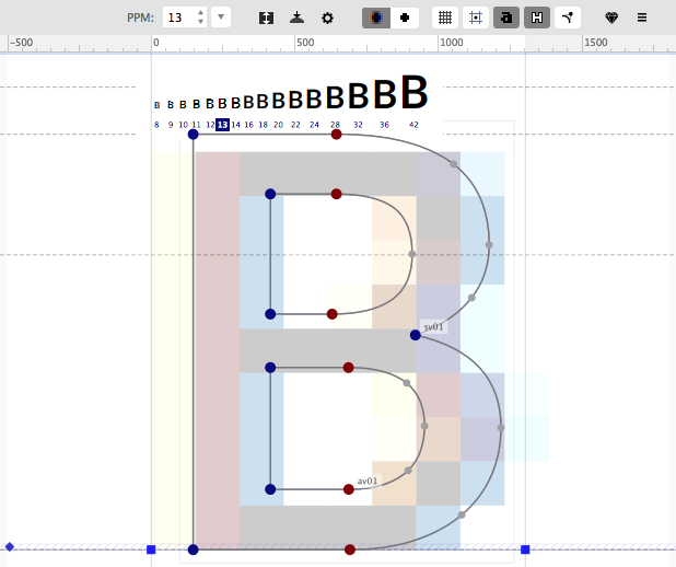
Once you are in the TrueType Hinting mode, the Property bar changes, and the Waterfall Preview and TrueType Hinting panel appear.
Hinting Property Bar»
The Glyph window Property bar is the main control center of the TrueType Hinting tool. It allows you to see various information layers in the Glyph window and to control all hinting parameters:

| Button | Description |
|---|---|
 |
Use the PPM controls to select one of the predefined values or enter your own value in the edit field. This allows you to see how outlines are rasterized at different sizes. |
 |
Opens the TrueType stems dialog box |
 |
Opens the TrueType alignment zones dialog box |
 |
Other hinting options including text preview sizes and text strings |
 |
Switches the pixel preview between black/white and ClearType - the real Windows system rasterizer. |
 |
Shows gridlines. Gridlines mark the edges of pixels that will appear in the selected PPM size |
 |
Shows centers of pixels. When the outline is filled, all pixels whose centers are on the outline or inside the outline are set black. This layer is very useful for delta hinting |
 |
Shows resulting pixel preview. FontLab uses the real TrueType rasterizer to preview a filled glyph at the selected PPM after interpretation of the instruction program |
 |
Shows hinted outline. The original, untouched outline of the glyph always appears in the Glyph window in black. The hinted outline, which is the result of the interpretation of the instruction program, appears in blue |
 |
Shows off-curve control points |
 |
Automatically hints the glyph and builds the instruction program |
 |
Local menu with additional useful hinting commands |
Waterfall Preview»
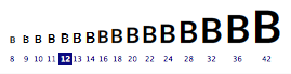
The waterfall preview at the top of the glyph shows how it will look when hinting instructions are applied:
| Unhinted “B” | Hinted “B” |
|---|---|
 |
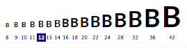 |
To select a size as PPM, double-click that size in the waterfall preview. You can also do this by using the PPM controls in the Property bar.
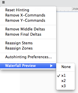
To change the zoom or completely hide the waterfall preview, use the Waterfall Preview submenu in the local menu :
TrueType Hinting Panel»
The TrueType Hinting panel automatically opens every time you select the TrueType Hinting tool. If you close the panel, switch to another tool, and select the TrueType Hinting tool again, the panel will reappear. The panel contains a local toolbar with main hinting tools on top, a waterfall preview of the current character in context on the left, and the code panel with hinting instructions on the right.

Toolbar»
With the TrueType Hinting toolbar you can select the hinting direction, the current visual instruction tool, open the code panel, and compile the instructions in it.
The buttons in the local toolbar are for the following operations:
| Button | Description |
|---|---|
 |
Set vertical direction. Sets visual instruction tools to work in the vertical direction. I.e. create vertical links, alignment, interpolation and deltas. Instructions in different directions are independent of each other |
 |
Set horizontal direction |
 |
Select the edit tool (E key) |
 |
Select Align command (A key) |
 |
Select Single Link command (S key) |
 |
Select Double Link command (D key) |
 |
Select Interpolate command (I key) |
 |
Select Middle Delta command (M key) |
 |
Select Final Delta command (F key) |
 |
Open the Code panel |
 |
Compile instructions in the Code panel |
Preview»
If you enter any characters in the edit field under preview, you will see these characters appear in the preview window. Use the usual FontLab rules to enter special characters (enter the character name after a slash “/” character or two slashes to enter a slash: “//”).
With the waterfall preview you can quickly select the current PPM. Just double-click the sample PPM you want to select.
Code panel»
To open the code panel, click  . It contains the code for visual TrueType hinting instructions. You can manually edit the code here and apply changes by clicking the button.
Alignment Instructions»
Alignment instructions are used to align points to the grid. There are two types of alignment instructions: those linked with alignment zones and those not linked with zones.
Alignment Zones»
Alignment zones define important vertical positions that are common to many font characters. A good example of an alignment zone is a baseline and the bottom position of the ‘O’ character:
At low PPM sizes you must set the bottom point of the characters ‘O’, ‘C’ and similar characters to the baseline to suppress the bottom overshoot. In this case we have a so-called bottom alignment zone.
Another example of an alignment zone is the top line of the ‘H’ character and the ‘O’ character:
Alignment zones are previewed in the Glyph window with a green and blue colors.
Editing TrueType Alignment Zones»
To add new TrueType zones or edit existing zones, click the Zones button on the local toolbar.
You will see the Alignment Zones dialog:
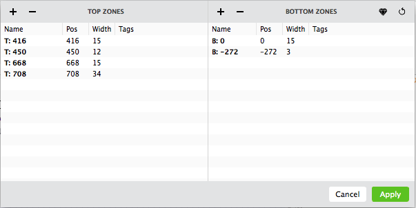
The dialog contains a toolbar, two lists of zones and a pair of buttons: Apply and Cancel. The left list stores all information about the top zones (where alignment happens in top-to-bottom direction) and the right list – about the bottom zones.
For each zone you may specify its name, position of the “snap to” line, the zone width and the tag.
To change settings for a zone, simply double-click the value in the list.
There is a toolbar above zones lists. Use it to call following commands:
| Button | Description |
|---|---|
 |
Add new top or bottom zone, respectively |
 |
Remove selected top or bottom zone |
 |
Automatically build zones |
 |
Reset zones |
AlignTop and AlignBottom Instructions»
These instructions are available only when the vertical hinting direction is selected.
To add AlignTop or AlignBottom commands:
- Select the Align tool .
- Position the cursor over the point that you want to align and click the mouse button.
- If the selected point was in one of the alignment zones, an AlignTop or AlignBottom command will be added to the hinting program. If the selected point is not in the zone, the “free” Align command will be added.
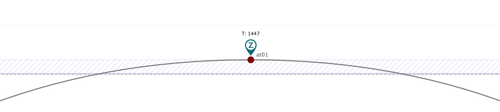
The AlignTop command appears as:
The AlignBottom command is similar to the AlignTop command.
How AlignTop and AlignBottom Commands Work
- In the prep program (this program interprets every time the PPM is changed) all alignment zones (stored in the cvt table) are aligned to the closest integer position.
- When the glyph program interprets, the position of the point aligned to the zone by the AlignTop or AlignBottom command is set equal to the aligned position of the zone if the scaled distance between it and the zone is no more than 16/17 pixels.
The AlignTop and AlignBottom commands have two arguments: the name of the point that is aligned by the command and the name of the zone. In the Code panel these commands appear as:
alignt at01 "T: 1447"
alignb ab01 "B: 0"
where at01 and ab01 are point names and “T: 1447“ and ”B: 0” are names of the top and bottom zones, respectively.
Hinting Alignment Zones»
By default the position of the alignment zones is scaled linearly. Sometimes this may not be satisfactory and you may need to exactly specify the position of the alignment zones at some PPMs.
With FontLab you can adjust the position of the zones around the linearly scaled position.
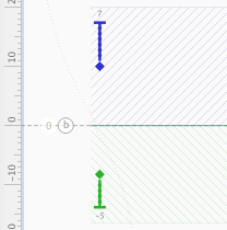
Every alignment zone has a blue or green icon at the left:
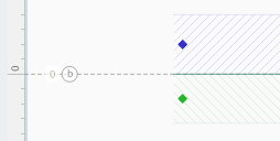
You can drag this icon up or down to adjust the position of the zone at the current PPM:
If you move the icon you will see all glyphs that have align commands applied to that zone changed their shape.
You may find this feature useful when you have to add glyphs to an already hinted TrueType font. New glyphs often have a different height at some PPMs and you can correct that with the zone alignment command and zone hinting.
Align Instruction»
Use the Align command when it’s not necessary (or possible – you can’t align points to horizontal alignment zones) to align a point to an alignment zone but you want to align the point’s position to the grid. The Align command is available in both directions.
The Align command allows you to directly control how point coordinates are rounded.
To set an alignment command on the outline:
- Select the Align tool .
- Position the mouse cursor on the point that you want to align.
- Click the mouse button. Hold the Shift key if you are setting vertical commands and the point is inside an alignment zone.
In the Code panel the Align command appears as:
alignv av01 round
alignh ah02 round
where av01 and ah02 are point names and round is the code of the alignment rounding method as shown in the table below.
To select a rounding method, click the Align instruction (blue circle with anchor) and the Options panel will appear:
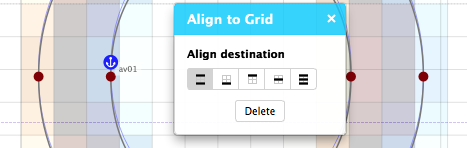
Select the align destination and close the panel to apply changes. You will see the code of the alignment rounding method will change in the Code panel.
Here is a graphical description of the various rounding methods:
| Rounding | Code | Description |
|---|---|---|
  |
round | Aligns to the closest grid line |
  |
left | Aligns to the left or bottom grid line |
  |
right | Aligns to the right or top grid line |
  |
center | Aligns to the closest center of pixel |
  |
double | Aligns to closest edge of pixel or center of pixel |
Align commands are the very first commands in any hinting program. They do not have base points and affect only one point.
Links»
Links are the most important visual commands. They are used to set relationships between outline points and to set distances between points to one of the standard stem values.
There are two types of links: single links and double links. Single links need to have a base point that is set by a previous command. This can be any command except a final delta.
A double link does not need to have base points. It sets the position of two points and they can be used as base points for a single link or interpolate command.
Standard Stems»
All link commands can be connected with one of the standard stems. When a link is connected to a stem it sets the distance between points to the scaled and rounded width of the stem. Using this technique you can implement standard-stem-based hinting, keeping important stem widths the same in every character in which they are used.
Please note that Type 1 standard stems and TrueType stems are different, although they function similarly. There is no limitation to the number of TrueType stems and they may be named.
Single Links»
The single link connects an outline point to a point whose position is set by another command. If you set a single link that linked point will always be at the given distance from the base point:
A single link may be linked with one of the standard stem widths. If it is so linked then the distance to the base point is replaced by the scaled and rounded stem width. So if several links are connected to the same stem width the distances from the base points will always be the same.
Single links are very straightforward: they have one base point and one affected point.
If a single link is connected with one of the standard stems the linking distance is always rounded to the grid. If the link is not so connected, then it may be rounded or not depending on the currently selected Round length option:
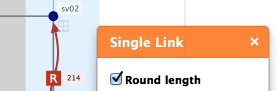
Rounding lengths is the default option for this command because it usually gives better control of the position of the destination point.
There is a special kind of single link called the aligned single link. It can be described as a combination of a single link and the Align command on the linked point. You can’t set a normal Align command at the end of the link but you can use an aligned link in this case. To make a link aligned switch on the Align destination option on the Options panel and choose the rounding method:
To set a single link:
- Select the single link tool .
- Position the cursor on the base point. Don’t forget that the position of the base point must be set by an instruction.
- Press the mouse button and drag the mouse to the point that you want to link. Release the button.
Hold the Shift key down if you do not want to connect the single link to a standard stem width. If you hold the Shift key the stem settings in the Options panel will be set to “None”.
Hold down the Alt key if you want to create the aligned single link.
Hold down the Ctrl key if you want to create the unrounded single link.
If the base point of the link is not aligned by some other command, FontLab will automatically set an Align command on it.
In the Glyph window the single link command appears as a directed red line with a mark in the middle (or without a mark if the link is not rounded). The mark is rhombus if the link is not connected to a standard stem width, and square with “R” if it is connected. If the link is connected, the stem name appears near the mark:
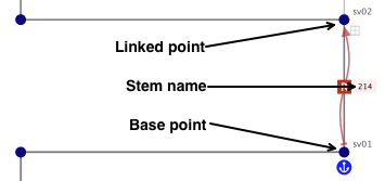
In the Code panel a single link command appears as:
singlev sv01, sv02 214 doublewhere sv01 is the base point; sv02 is the linked point; 214 is the name of the stem to which this link is connected (or “.round” if it is not connected to the stem or “.none” if the Round length option is off); and double is the method of alignment for aligned links.
Customizing the Single Link Command»
There are two ways to customize the single link command: the Options panel and the Code panel.
To customize a command with the Options panel, click the link red line:
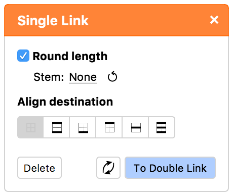
Use the Delete command to remove the command and the other options to customize it. The Stem sub-menu lets you link the command to one of the stems.
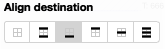
The Align Destination option is the same that you can see in the Align command’s Option panel and defines the rounding method of the destination position:
| Rounding | Code | Description |
|---|---|---|
 |
do not round | Alignment is off |
|
round | Aligns to the closest grid line |
|
left | Aligns to the left or bottom grid line |
|
right | Aligns to the right or top grid line |
|
center | Aligns to the closest center of pixel |
|
double | Aligns to closest edge of pixel or center of pixel |
You can click the Reverse button, denoted by  , to reverse the direction of the link, and on To Double Link button to convert the single link to the double link instruction.
In the Code panel, you can edit the link instruction directly and click the Compile button to apply changes.
Double Link»
Double links let you set the distance between two “untouched” points. Both points will be moved by this command and both points will be touched afterward.
The distance between points can be connected to one of the standard stem widths using the usual procedure described above. If the distance is connected to the stem width, it will scale with the stem.
You can’t predict where points will move that are connected by a double link so we recommend that you use this command only for stems for which the position is not very important or for stems that will be used as the basis for hinting.
The double link command does not have base points, but it sets the position of points.
To set a double link:
- Select the double link tool .
- Position the cursor over one of the points you want to link. Press the mouse button.
- Drag the cursor to the point you want to link to the first point. Release the button.
Hold the Shift key down if you do not want to connect the double link to a standard stem width. If you hold down the Shift key the stem settings in the Options panel will be set to “None”.
Hold down the Ctrl key if you want to create the unrounded double link.
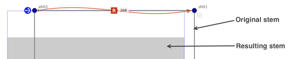
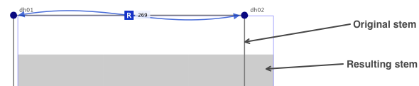
In the Glyph window the Double link command appears as a blue line with two arrows and a mark in the middle. The mark is a square with “R” if the link is connected to the stem, and a rhombus if it is not connected. If the link is connected the stem width will appear near the mark:
In the Code panel a double link command appears as:
doubleh dh01, dh02 269where dh01 and dh02 are points that are linked; and 269 is the name of the stem to which this link is connected (or “.round” if it is not connected to the stem or “.none” if the Round length option is off).
Customizing the Double Link Command»
There are two ways to customize Double link: the Options panel and the Code panel.
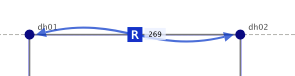
To customize a command with the Options panel, click the link blue line:
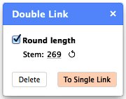
Use the Delete command to remove the command and the other options to customize it. The Stem sub-menu lets you link the command to one of the stems.
You can also click the To Single Link button to convert the double link to the single link instruction.
In the Code panel, you can edit the link instruction directly and click the Compile button to apply changes.
Interpolation»
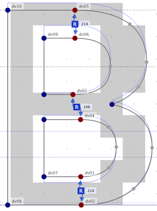
Most of the time, the align and linking commands are enough to hint most characters, but in some cases a very different kind of command is necessary. Look at the enlarged middle-right region of the character B in the vertical direction:
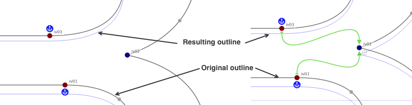
You can see that point iv02 in the original outline in the vertical direction is set exactly between points iv01 and iv03. But because these points are aligned and point iv02 is not controlled it becomes too close to point iv03.
In this and similar cases you can use the interpolate command. This command sets the position of a point in the same proportion between two other points as it was in the original outline.
Or the intermediate point could be aligned to he grid and serve as the starting point for a single link or another interpolation command.
This command has two base points (iv01 and iv03 in our sample) and one affected point (iv02).
To set the interpolate command:
- Select the interpolate tool .
- Click the first base point.
- Click the point to interpolate.
- Click the second base point.
Hold down the Alt key if you want to create the aligned interpolate command.
In the Glyph window the interpolate command appears as two green directed lines from the interpolated point to base points.
In the Code panel the interpolate command appears as:
interpolatev iv02 iv01, iv03where iv02 is the interpolated point and iv01 and iv03 are the base points.
To delete the command, click the green interpolation line and then click Delete in the Options panel.
The Align Destination option is the same that you can see in the Align command’s Options panel and allows to align the destination point to the grid.
Delta Instructions»
Now you know all about the visual hinting commands that can be applied to an outline at all PPMs. In addition to these commands the TrueType hinting language lets you set special commands that will work only at specific PPM sizes. These commands are called delta instructions.
There are two delta instructions for each hinting direction: middle delta instructions and final delta instructions.
Middle Delta Instructions»
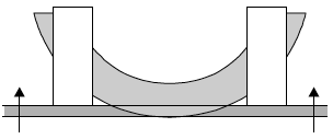
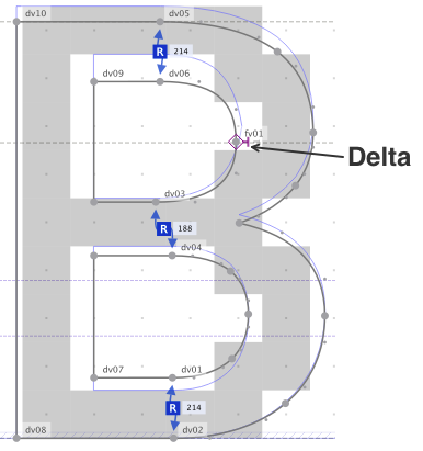
A middle delta instruction can move outline points like any other instruction. It can move any outline point in ⅛-pixel increments from one pixel left (or bottom) to one pixel right (or top):

Middle delta instructions are interpreted like other commands in the hinting program. They are automatically inserted between “normal” instructions that move points and so can be used to modify the normal interpretation of the hinting program:
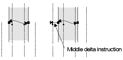
In the example above, the vertical stem is moved one pixel to the left when the middle delta instruction is applied.
A middle delta instruction may be applied to a touched or untouched point and the point becomes touched afterwards.
It’s a good idea to use middle delta instructions to correct the rounding direction on some PPMs, like on the character ‘e’ at small PPM sizes.
Another good application of middle delta instructions is the correction of diagonal hints. A middle delta instruction “touches” the point to which it is applied, so any other point between two delta instructions will be interpolated in the final interpolation routine.
To set a middle delta instruction:
- Select the Middle Delta tool .
- Move the cursor to the point at which you want to set the delta instruction, press the left mouse button and drag to the needed direction.
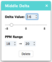
The middle delta instruction has 4 arguments: point to move, PPM0, PPM1 (the PPM range in which this instruction works), and the shift distance in eighths of pixels. In the Code panel this instruction looks like:
mdeltav mv01 18-20 -6where mv01 is the point name, 18–20 is the PPM range, -6 is the distance to move (in this case – move down by ¾ of a pixel). This means that point mv01 will be moved down ¾ of a pixel when PPM is 18, 19 or 20.
By default the PPM range is equal to the current PPM. You can edit the middle delta instruction right in the code or in its Options panel:
Active and Inactive Delta Instructions»
Delta instructions may be active or inactive. When the current PPM is within the PPM range of the delta instruction the instruction is active. Otherwise it is inactive.


Note
If you set a new middle delta instruction at a point where a delta instruction is already set and is active the old instruction will be replaced by the new one. If you set delta instructions for the same point and with the same shift distance but for different PPM ranges FontLab will try to combine PPM ranges and unite delta instructions where it is possible.
Final Delta Instructions»
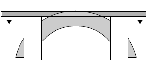
Final delta instructions are applied after the final interpolation of all untouched points. They are used as a last resort to shift points to remove or add pixels at PPM sizes where it is still necessary after application of zones, stems and all other hints:
 |
 |
|---|---|
| Hinted character at 12 PPM without delta instructions | Same character with delta instruction |
The sequence of interpretation is the only difference between middle and final delta instructions. They work exactly the same way. To set final delta instructions, select the final delta tool and follow the same instructions as above for middle deltas.
Some recommendations:
- Delta hinting is a very time-consuming operation because you have to check the rendering results at many PPMs. So always try first to get the best possible results from normal, linear hinting.
- Use the waterfall preview in the TrueType Hinting panel to see where delta hinting is necessary.
- Try to set as few delta instructions as possible. They increase font size and complexity.
- It’s better to set one delta instruction with a larger range than two less comprehensive delta instructions.
Removing Instructions»
You can remove hinting instructions using three methods:
- Select the instruction in the Code panel and press the Del key.
- Click the instruction and then on Delete in the instruction’s Options panel.
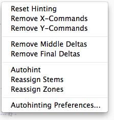
- Right-click in the Glyph window when the TTH tool is active and choose one of the commands in the context pop-up menu: