Contour tool»
The Contour tool is used for normal editing of the contours. It is the default tool in Fontlab VI, and the first item on the toolbar. It is selectable using the A key or the Contour arrow on the Toolbar.

It is distinct from the Element tool (the second arrow, after the Contour tool), which is only used for dealing with an entire Element.
Important
Always use the Contour tool instead of the Element tool, unless you are sure you need to work at the Element level!
The functions of the Contour tool require that you already have outlines drawn. You need to either create a font, or open an existing font, before using this function.
Temporarily Activating the Contour tool»
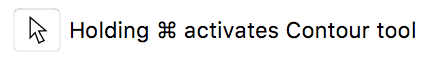
There are two methods to temporarily activate the Contour tool while you are using another tool: holding down the A key, or holding down the Cmd key. The first mode is active by default, and that means that you can press and hold the A key while using most tools to temporarily activate the Contour tool. To use the Cmd key mode, open the Editing page of the Preferences dialog box and turn on this option:
When this option is active, you can temporarily activate the Contour tool by pressing the Cmd key on the keyboard. Releasing the Cmd key will return to the tool you were using before.
Hit-to and Snap-to Distances»
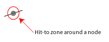
When you need to select a node or any other object on any of the layers, you need to click it with the mouse. You don’t need to click the object precisely, but you must be within a certain distance for the object to get selected. This distance is called the “hit-to distance”.
By default the hit-to distance is set to 3 screen pixels for nodes and 4 screen pixels for guidelines, but you can change it on the Distances page of the Preferences dialog box.
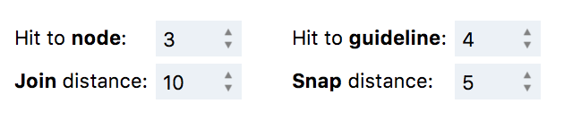
If you are moving an object close to another object, for which the Snap-to feature View > Snap is activated, the first object snaps to it even if you don’t move the first object precisely to touch the latter. By default, the snap-to distance is set to 5 screen pixels, but you can change it on the Distances page of the Preferences dialog box.
Selecting Nodes and Contours»
To select an individual node, move the mouse cursor close to it and click. The selected node will appear red in color.
To select several nodes, Shift-click on them. Segments between selected nodes will be selected as well. To remove nodes from the selection, Alt-click (or Cmd-click) on selected nodes.
To select an individual segment, move the mouse cursor close to it and click. The selected segment with two nodes will appear red in color. You can turn this off on the Editing page of the Preferences dialog box.
To marquee select part of a contour, click in the empty space and drag around the area which you need to select. Use Shift to add to the selection or remove from it. Alt-drag for a freeform marquee selection. Marquee selection does not select handles (off-curve points), but this can be changed on the Editing page of the Preferences dialog box.
To select the whole contour, double-click on the contour or Alt-click on the white space near the contour. Use Shift to add to the selection or remove from it.
Moving Nodes»
To move individual nodes:
-
If nodes are hidden, switch nodes on with the View > Show > Nodes command, or click on the node to select it. If you miss, and accidentally select an incorrect node, use the Page Up and Page Down keys to move to the correct node.
-
Drag the node to its new place. It will stick to the other objects if they are visible and snap-to those objects, where that feature is activated (View > Snap menu). Hold down the Shift key to move it vertically or horizontally.
While you are dragging the node you may see red dotted lines with arrows at their ends. These are snapping suggestions which help you position objects better:
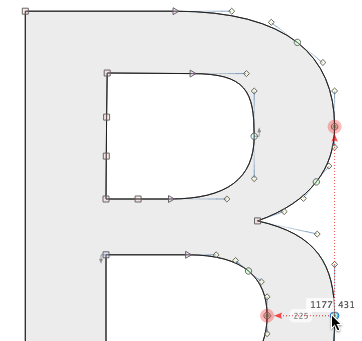
Press Ctrl at any time when dragging points to temporary disable snapping and snapping suggestions.
Options»
If you are moving a node that is connecting two PostScript (Bézier) curves you have the following options:
-
If the connection of the curves is smooth, press the Alt key to constrain movement to a line between the curves’ control points:
-
If the connection is sharp, press the Alt key while dragging the node to move it without moving the adjacent control points:
-
If the connection is smooth, press the Alt and Cmd keys to keep the connection’s curvature optimised. All 4 control points will be involved in the process:
-
Press the Alt and Shift keys to slide the node along a segment. The control points will be recalculated to keep the current shape of the segment:
-
When you are editing control points of a Bézier curve, press the Shift key before clicking the button to keep the direction of the control vector unchanged:
-
If you are moving a control point of a curve with a sharp connection, press the Alt key to temporarily change the connection type to smooth, so that the adjacent control vector will be collinear.
-
If you have a node or handle that is nearly aligned (in either X or Y) with an adjacent node, Shift-double-click on the node or control point and it will shift to become aligned.
Do not forget that you can press the ` key (usually the key between Shift and Z) at any time to get an instant high-quality preview of the glyph outline as it will print.
Changing Node Types»
The type of connection between segments is very important in maintaining the smoothness of contours. Connections can be of two types: smooth and sharp (non-smooth).
To make connection marks visible, click on the  button on the Toolbar.
If a connection is smooth, the direction of the adjacent curve control vectors or of the curve control vector and line is collinear and the contour is smooth at the connection.
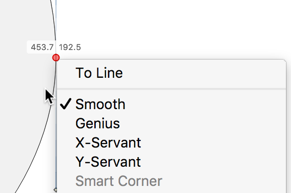
To change the type of connection, double-click on the node or Ctrl-click the node and select the connection type in the popup menu:
Modifying Segments»
Sometimes you may want to modify a contour in a more flexible way than by moving nodes. For example, to adjust the shape of a curve in node editing you would usually make the control points of a curve visible and move them to modify the curve. A more intuitive way would be to “grab” the curve somewhere between the nodes and move this imaginary “inside” point. The curve’s shape changes accordingly. We call this method “non-node editing”. This means that you can not only move nodes, but every point of a glyph’s contour. You can even switch off nodes and still be able to edit the contour as you wish.
To modify a curve or line segment using the non-node editing method:
- Move the mouse cursor onto the place on the segment that you want to move.
- Press the mouse button. You will see a small color point that will show you the temporary point that you are moving.
- Drag the mouse and observe how the shape of the curve changes. After a few experiments (which can be undone) you will have enough experience to use this method of editing.
Several notes that you should remember:
- In non-node editing, guiding objects are sticky. So, temporary points snap to the grid, guidelines, hints or anything else.
- If you choose a temporary point near one of the ends of a curve, you will move that end, not just change the curve’s shape. This is a useful method to locate a curve’s endpoints.
- When you press the mouse button to begin non-node editing you will see that the endpoints of the curve as well as the control vectors appear, simplifying the editing of this segment.
- If you drag a “point” on a curve, its control vectors may change direction.
Converting Segments»
CtrlAlt-click near a line segment to convert the segment to a curve segment. CtrlAlt-click near a curve segment to Balance the segment (make both handles proportionally the same length). To convert a curve segment to a line segment, simply remove one of its handles using Edit > Delete (Backspace).
Inserting Nodes»
To insert a new node on a segment with the Contour tool:
- Position the mouse cursor on the segment where you want to insert the node.
- CtrlAlt-click where you want the node to be inserted or ShiftCtrlAlt-click on a segment to add an extremum node to that segment.
You can also use the Knife tool to insert nodes.
Deleting Nodes and Handles»
To delete nodes and handles using the Contour tool, click on the node or the control point to select it, and press Backspace (or Del key on small keyboards). The node or the handle will be removed. Or Ctrl-click on the node and select the Delete node command in the context menu for the same result. In these two cases, FontLab VI tries to keep contours closed. On the other hand, using the Del key (FnDel keys on small keyboards) doesn’t delete the selected node, but breaks the contour.
Another one way to delete the handle is to ShiftAlt-click on it.
Deleting Segments»
To delete a line or a curve, click on it with the Contour tool and then select the Delete command in the Edit menu (Backspace key). This method removes the segment with both its nodes but doesn’t break the contour. On the other hand, if you wish to leave both end nodes intact, but break the counter, then you can delete the segment using the Del (FnDel) key as well.
Special Features»
- Hold Ctrl at any time when dragging Points (Handles or Nodes) to disable snapping and snapping suggestions.
- Tap ShiftC key or use the Contour > Power Nudge menu item to toggle the Power Nudge mode. With Power Nudge on, when you drag some points, FontLab will automatically guess which other points should be moved. This works well most of the time. If Power Nudge is off, you can enable it temporarily (while dragging) when you hold the C key (without Shift).
- Tap L key or use the Contour > Tunni Lines menu item to toggle the Tunni Lines mode. With Tunni Lines on, you can move both handles on a curve in sync. The results will balance their proportions and tune the curve tension.
The Summary»
Canvas (drawing area)
- Alt-click near a segment to select the entire contour.
- ShiftAlt-click near a segment to add the entire contour to the previous selection, or remove it from the selection.
- CtrlAlt-click near a line segment to convert the segment to a curve segment. CtrlAlt-click near a curve segment to Balance the segment.
- To perform a rectangular marquee selection, Drag on the canvas to select multiple Nodes and/or Handles. Alt-drag for a freeform marquee selection. You can also hold down Shift, to add to the previous selection or remove from it.
- Click on the canvas to deselect.
Segment
- Drag on an unselected segment to edit the segment.
- Click on a segment to subselect the segment, i.e. select only the segment, not the entire contour.
- Alt-click on a segment, or double-click on a segment to select the entire contour.
- ShiftAlt-click on a segment, or Shift-double-click on a segment to add the entire contour to the previous selection or deselect it.
- CtrlAlt-click on a segment to add a Node in that position.
- ShiftCtrlAlt-click on a segment to add an extremum Node to that segment (if it’s needed).
- Alt-drag on a selected segment to duplicate it.
- With one or more segments selected, tap Backspace to merge their adjacent Nodes, i.e. remove them and try to keep the path unchanged.
- With one or more segments selected, tapping Del or FnBackspace will break the contour at the Nodes adjacent to the segments and delete these segments.
Node
- Click on a Node to select it. Shift-click on a Node to add to the selection. Alt-click on the selected Node to remove from selection.
- Double-click on a Node to convert it between Sharp and Smooth. If the Node is between a Curve and a Line segment, a Sharp Node will be converted to Tangent.
- Alt-double-click on a Sharp Node to Normalize its sharpness. This will change all Handle positions on both adjacent segments so that you get a “natural” corner.
- ShiftAlt-double-click on a Sharp Node to convert the node into a Smart Corner. A Smart Corner can produce a rounded corner or an inktrap. It’s live and non-destructive, and you can change the radius of the Smart Corner. If you double-click on the Smart Corner, you can change the radius of all Smart Corners in the current element. Right-click on a smart corner to Apply it, i.e. convert it to a regular contour with the rounding or inktrap applied.
- Alt-double-click on a Smooth Node to Harmonize its position i.e. equalize the Curvature on both sides of the Node.
- ShiftAlt-double-click on a Smooth Node to convert the Node to a Genius Node (one that will always remain harmonized even if you move the handles).
- Drag a Node to move it and its associated Handles. This also works with multiple selected Nodes.
- Shift-drag a Node to move it and its associated Handles along the horizontal or vertical axis. This also works with multiple selected Nodes.
- Alt-drag a Node to move it but keep its Handles in place (also works with multiple selected nodes).
- CtrlAlt-drag a Node to move it, and proportionally nudge all Handles of both adjacent segments. This also works with multiple selected nodes.
- AltCmd-drag a Smooth Node to move it and Normalize its smoothness. This also works with multiple Smooth Nodes. When smoothness is normalized, all Handles of both adjacent segments are recalculated so that “best” smoothness is achieved. This is equivalent to Fontographer’s “Auto-Curvature” functionality. Note that this doesn’t work for editing TrueType curves.
- ShiftAlt-drag a single Node to slide it along a segment. The Handles will be recalculated to keep the current form of the segment. If it’s a Smooth Node, you can slide it only within the current segment. If it’s a Sharp Node or a Start/End Node of an open contour, you can continue sliding it outside the current segment (i.e. smartly extend the segment). This does not work for multiple Nodes.
- With one or more Nodes selected, tap Backspace to merge these Nodes, i.e. remove them and try to keep the path unchanged.
- With one or more Nodes selected, tap Delete or FnBackspace to Break contour at these Nodes, or to break the contour and delete the adjacent segments. This is controlled in File > Preferences > Editing. We recommend the first setting (“break contour”) because with this setting, if you select some nodes and tap Del once, the contour will be broken, and if you tap Del again, then the segments will be deleted.
Handle (BCP)
- Click on a Handle to activate it. Shift-click on a Handle to add to the selection.
- ShiftAltclick on a Handle to retract it.
- Double-click on a Handle of a Sharp Node to align its angle to the opposite Handle.
- Shift-double-click on a Handle of a Sharp or Smooth Node to align its angle to the closest horizontal or vertical axis.
- Alt-double-click on a Handle of a Smooth node to slide the Node to the closest extremum.
- Drag a Handle to move it. Also works with multiple selected Handles.
- Shift-drag a single Handle to move it without changing its angle. This does not work for multiple Handles.
- Shift-drag multiple selected Handles to move them along the horizontal or vertical axis.
- Alt-drag a Handle to also move its opposite Handle. For a Sharp Node, it aligns the opposite Handle to the same angle. For a Smooth Node, it also puts the opposite Handle at the same distance to the Node. Also works with multiple Handles.
- With one or more Handles selected, tap Backspace or Delete to convert a Curve Segment to a Line Segment.