Effects»
You can use one of FontLab’s many Effects to change the font’s appearance. Some are purely functional, others are much more experimental. The Effects are not a replacement for the work of a professional type designer, but they’re fun to use.
Effects may be found under the Tools > Actions menu.
Bold/Change Weight»
The Bold/Change Weight effect precisely changes the weight of a glyph’s stems. It can be used to make the contours in the selected layer bolder or thinner. You can use Bold/Change Weight as a starting point for making a new weight (or perhaps a Master) for your font.
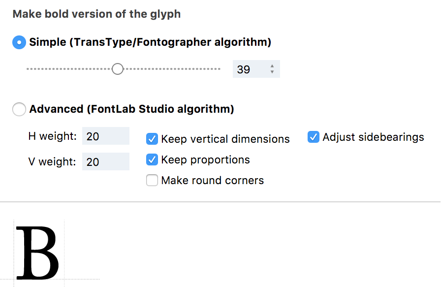
The Simple algorithm (from TransType/Fontographer) uses information about the standard thicknesses in the font (from File > Font Info > Master Properties > Stems) to determine how much to change the relative proportions of horizontal and vertical thickness while changing weight.
The Advanced (Fontlab Studio) algorithm offers more options for tweaking.
-
Enter the values for H weight, or horizontal weight, and V weight, or vertical weight, to control how much to increase (use positive numbers) or decrease (use negative numbers) the weight of the outline.
-
Checking Keep vertical dimensions ensures that even after the weight of the glyphs changes, they still sit on the same horizontal position. All changes in height are on the top. The results of this function are precise for uppercase and lowercase letters, but small caps may suffer some change if their height is not the same as the x-height.
-
Keep proportions
-
Checking Adjust sidebearings will preserve the sidebearings of the modified glyph(s) when there is a change in the width.
-
Switch on Make round corners to make rounded corners in the new outline.
Note that the weight-changing values are in font units, so the visual effects of this action depend on the font’s UPM value.
Outline»
The Outline effect converts contours to strokes and uses these strokes to build parallel contours. You can adjust the thickness of the stroke using the slider:
You can use the miter icons to change the treatment of contour corners (and the ends of open contours). For example, flat contour ends versus round ends.
There are three types of joins: miter, round, and bevel. Miter joins extend the outer edges of the lines until they meet at an angle, similar to the corners of a picture frame. Round joins draw a circle with a diameter equal to the stroke width at each bend. Bevel joins are drawn as if the joining segments were stroked with butt cap ends and the resulting notch is filled with a triangle.
Shadow»
Generates a drop shadow. This effect that can save a lot of time and work.
The Shadow effect presents the following options:
- angle parameter sets the direction of the shadow (positive values are to the right and up)
- thickness defines the outline thickness
- distance controls how far away the shadow will be shifted. Use the slider or horizontal and vertical values.
3D Extrude»
This effect creates a “3D” version of the glyph. This action is similar to the Shadow action but it simulates a 3D thickness of the glyphs:
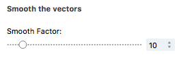
Smooth»
Turns glyphs’ straight lines into curvy ones. The Smooth effect allows you to adjust only the amount of “smoothness”.
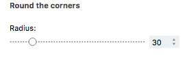
Round»
Creates a “rounded corners” effect using the corner radius. The results are imperfect and probably would require manual outline editing to get credible results.
Sharp»
Adds pointy corners (reverse ink traps) to outlines:
Distort»
Applies a random distortion to outlines. This effect is randomly different each time, even with the same Force value, so you can run the process multiple times to get different results:
The Distort effect allows you to adjust the amount of Force used to distort your contours.
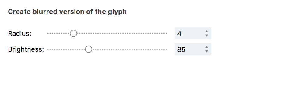
Blur»
Applies a Gaussian blur to outlines. You can control the Radius and Brightness of blur.
Perspective»
Perspective is a geometric slant of the vertical glyph plane back or forth. There is a slider to the right of the ‘m’ glyph image which can be used to rotate your glyph in 3D space. Move it up to make glyph’s top edge closer to you or move it down to make glyph’s top edge farther. The glyph will be rotated around imaginary 3D axes. The vertical axis is interpreted as the middle of the glyph.
Drag the glyph’s bounding box corners to change perspective arbitrarily. It is also possible to change glyphs’ image height and/or width without changing perspective. Note that this “scaling” effect is applied to glyph images only but doesn’t change their metrics.
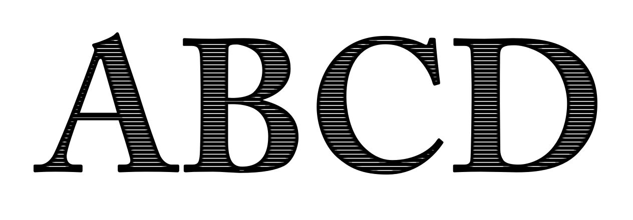
Engraving»
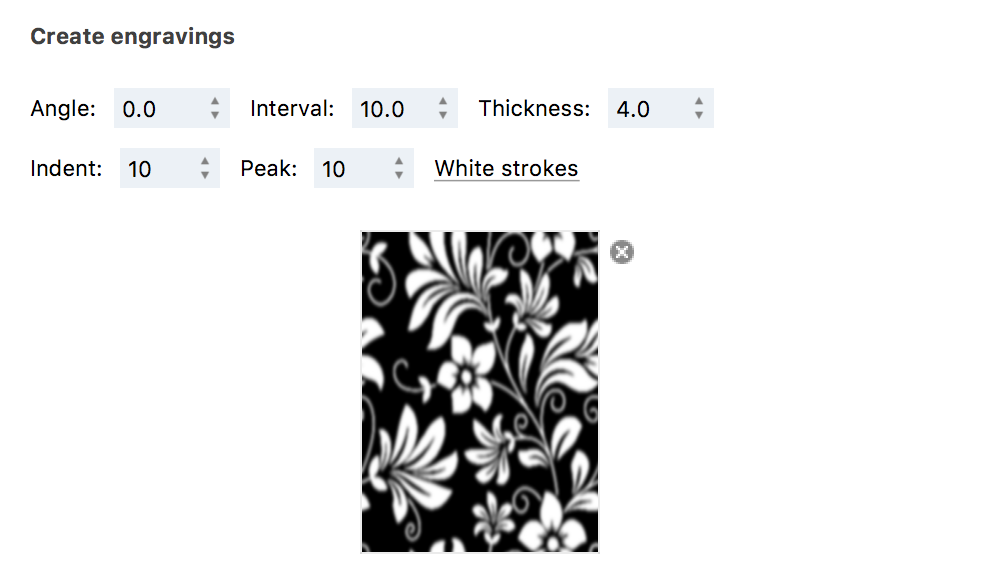
Applies an engraving effect on the glyph based on the values entered for the following options:
- angle sets the angle of the engraved strokes
- interval defines the distance between two engraved strokes
- thickness describes the thickness of each stroke
- indent is the distance of the engraved strokes from the outline of the glyph
- peak defines the length of the peak of a strokes; larger values for peak make strokes sharper
- color parameter lets you choose between black or white as the color of the engraved strokes
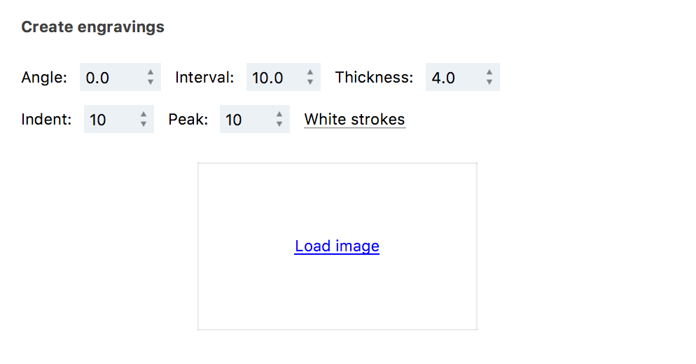
You can also use the Load Image operation to import an image file into the dialog box. This image will mask the engravings that will be applied to the glyph.
For example, applying the following image
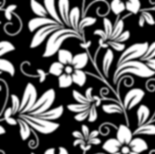
will produce this result:
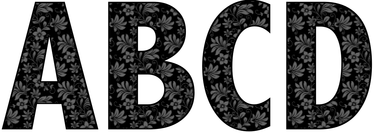
You can remove this image by clicking on the cross icon to its right.
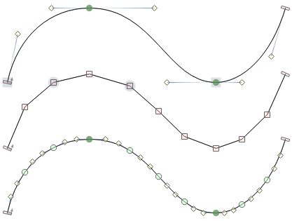
Add Nodes»
The Add Nodes effect creates more nodes on the contour. It puts a node every x units, where x is the segment length value you entered.
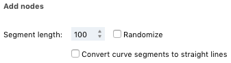
You can also choose to convert curve segments to vectors if needed.